|
Leosac
0.8.0
Open Source Access Control
|
|
Leosac
0.8.0
Open Source Access Control
|
This page describes how to set up a Raspberry 1 with a Wiegand reader, step by step. It is not the recommended approach in production but can be useful in lab for tests purpose. We recommend to use dedicated PCB hardware connected for the Raspberry Pi (or any other pico-pc) or to go with Installation Guide (part 2): Raspberry Pi (1 B+ or 2 or 3 or 4) + Piface Digital (1 or 2) + Wiegand Reader
General infos
Here is the Raspberry Pi GPIO layout for informations:
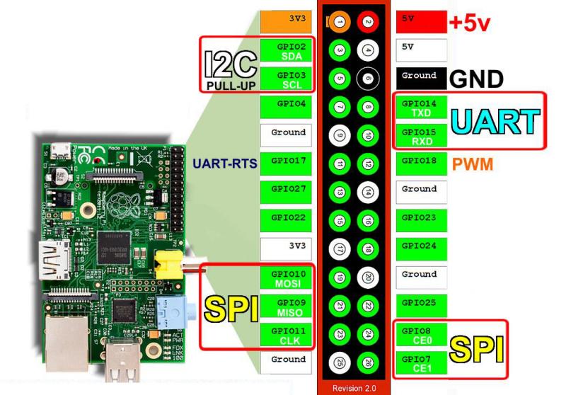
A Wiegand reader will usually use +5V as its "high" voltage level. However, Raspberry Pi's pins are built to deal with 3.3V current. Therefore we need to reduce the voltage in order to not damage the pins.
We want to go from +5V to about +3.3V: Vin = +5 and we would like Vout = +3.3.
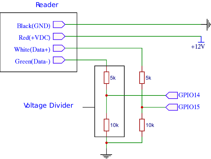
The values on the resistors are not strictly fixed. As long as the ratio between the upper and lower resistor value is 1/2 for the voltage divider, the 5k resistor can be safely replaced with another in the range from 2k to 10k depending on what you have. If you only have 10k resistors, you could even put 2 in series to obtain 20k.
Do not forget to plug the reader on a 12V current source. 5V is also suitable with some readers if you don't have another choice but is less recommended.
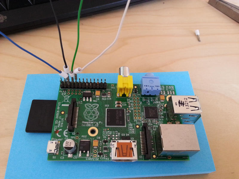
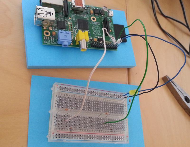
Raspberry Pi with wires connected to GPIO.
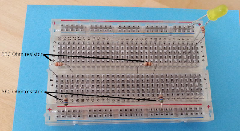
We will use 2 resistors type: R1 = 330 and R2 = 560. This gives Vout = 3.146, which is acceptable.
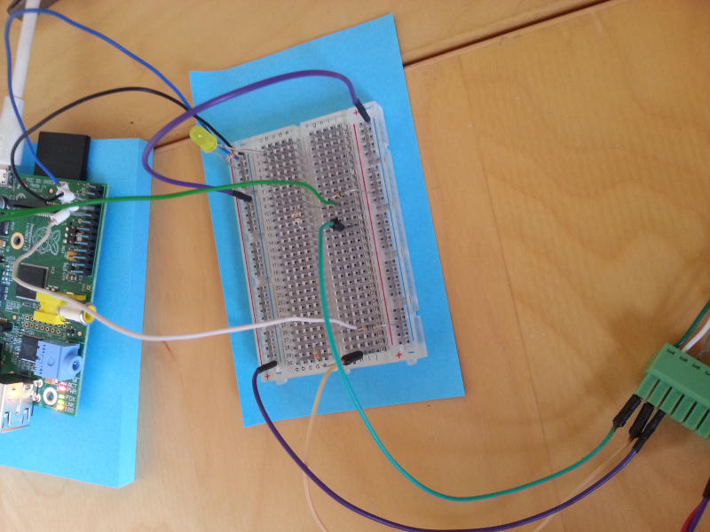
This is what the breadboard look like, with 4 resistors for voltage divider. The led will be lighted if an access control is successful.
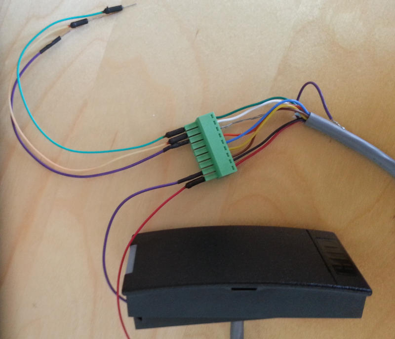
The reader could be powered by the Raspi's 5V pin, but we use an external powering source.
We then plug the raspberry pi's wire (connected to the GPIOs) into the board. This will allow us to retrieve data from the reader as well as powering the led when we need to.
You're done for the hardware setup. If Leosac is already installed, you can now setup the Module: SysFS GPIO and Module: Wiegand.
You may want to use 74LVC244 / 74LVC245 or CD4049 / CD4050 CMOS devices instead to convert 5V signal to 3.3V in a more professional way.
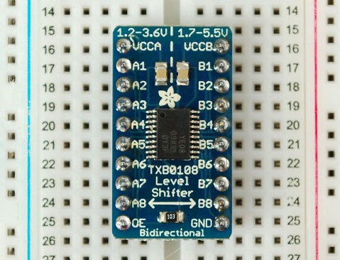
When working with a breadboard you may even want to use Level-Shifter 8-Channel (or 4 channel, just be sure input is 5V and output 3.3V).
 1.8.17