|
Leosac
0.8.0
Open Source Access Control
|
|
Leosac
0.8.0
Open Source Access Control
|
An explanation of how hardware modules work together.
Since the main goal of Leosac is to handle access control of physical object (mainly doors), and because it reads data from specific hardware (various wiegand reader) we can say that the hardware plays an important role in the project.
We must be able to interface with various devices, in various setup. A strong abstraction of the hardware is in place. This allows easy and flexible configuration for the end-user, and help with maintaining and expanding the code.
As you probably already know, Leosac is built around modules (aka shared library). Leosac module are more than just plugins. They do not extend core functionalities, they provide them. If you do not start any module, Leosac will be useless and will literally sleep forever.
The core infrastructure is designed to support modules and provide facilities for them to communicate with each other. Modules communicate using message-passing: libzmq (and the C++ binding: zmqpp) are used to implement this message passing. Various specifications about how messages are supposed to be formatted and the expected interaction between components are defined through the project.
This is a graphic overview of hardware modules. The GPIO module can be changed without impacting the other modules on top if it, provided that it properly implements the specifications.
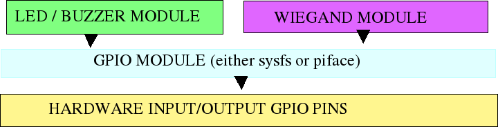
So, let's see how this module based architecture impact hardware management. Let's suppose we want to control a Wiegand card reader: This means that we must be able to read a card number from it, and that must be able to control the device's led and buzzer.
We can see our wiegand reader as multiple sub-components:
data0 input PIN.data1 input PIN.We can go a bit lower and identify other sub-components:
data0 input PIN.data1 input PIN.data0 and data1 are GPIO input PIN already.
There are 4 kind of hardware here: GPIO, Led, Buzzer and Wiegand Reader. Led and Buzzer are implemented as one. We have (at least) one module per device type. A module for a specific hardware provide support for it.
The LED module requires that a GPIO module exposes the GPIO to the application in order to work. Same goes for the Wiegand module. GPIO can be provided by 2 modules: Through the PifaceDigital card, or through sysfs. The other do not care what module handle the GPIO. As long as one of them do, and respects the specifications.
So, in our example, here is what happens when a card is presented to the reader:
doorman module picks this up, and eventually open a door.You can find below the specifications that must be implemented when writing a module that provide support for some kind of hardware.
A module that implements GPIOs support must:
input / output pin and let them associate a name per GPIO.A facade object, FGPIO implements client-code (requests) of those specs, and the module must implement the server-code (responses).
We define 4 commands that can be send to a GPIO device:
This is used to query the state of the GPIO pin.
Request:
| Frame | Content | Type |
|---|---|---|
| 1 | "STATE" | string |
Response:
| Frame | Content | Type |
|---|---|---|
| 1 | "ON" or "OFF" | string |
This turns the pin high. It accepts an optional duration parameter. If set, this parameter express the duration for which the GPIO shall stay high. This duration is expressed in milliseconds. The module shall turn the GPIO off after this duration has expired.
Request:
| Frame | Content | Type |
|---|---|---|
| 1 | "ON" | string |
| 2 | 3500 | int64_t |
Response:
| Frame | Content | Type |
|---|---|---|
| 1 | "OK" or "KO" | string |
This turns the GPIO low. There is no parameter.
Request:
| Frame | Content | Type |
|---|---|---|
| 1 | "OFF" | string |
Response:
| Frame | Content | Type |
|---|---|---|
| 1 | "OK" or "KO" | string |
Toggle the GPIO, setting it to low it was set to high, and vice versa. This command takes no parameter.
Request:
| Frame | Content | Type |
|---|---|---|
| 1 | "TOGGLE" | string |
Response:
| Frame | Content | Type |
|---|---|---|
| 1 | "OK" or "KO" | string |
A module that implements LED devices support must:
Note that some GPIO commands are also valid LED command.
We define 5 commands that can be send to a LED device:
ON command for GPIO.ON command for GPIO.TOGGLE command for GPIO.Shall return the state of the LED device.
Request:
| Frame | Content | Type |
|---|---|---|
| 1 | "STATE" | string |
Response:
| Frame | Content | Type | Comment |
|---|---|---|---|
| 1 | "ON" or "OFF" or "BLINKING" | string | - |
| 2 | BLINK_DURATION | int64_t | Only if frame 1 is "BLINKING" |
| 3 | BLINK_SPEED | int64_t | Only if frame 1 is "BLINKING" |
| 4 | "ON" or "OFF" | string | Only if frame 1 is "BLINKING" - indicate the current value when the command was received. |
This makes the LED blink, useful for controlling your christmas tree. The BLINK command accepts 2 optionals parameter: a duration and a speed. Both are expressed in milliseconds.
The second frame shall contain the duration (use -1 for infinite blink) and the third frame the speed.
Request:
| Frame | Content | Type | Comment |
|---|---|---|---|
| 1 | "BLINK" | string | - |
| 2 | BLINK_DURATION | int64_t | Optional. In milliseconds. |
| 3 | BLINK_SPEED | int64_t | Optional. In milliseconds. |
Response:
| Frame | Content | Type |
|---|---|---|
| 1 | "OK" or "KO" | string |
Buzzer and LED share the same code. See the led module specifications.
A wiegand reader device shall have 2 inputs GPIO configured and optional greenled and buzzer devices.
A wiegand device shall accept 4 commands:
Make the reader beep for a given duration. The duration is expressed in milliseconds.
Request:
| Frame | Content | Type | Comment |
|---|---|---|---|
| 1 | "BEEP" | string | - |
| 2 | BEEP_DURATION | int64_t | In milliseconds. |
Response:
| Frame | Content | Type |
|---|---|---|
| 1 | "OK" or "KO" | string |
Turn the buzzer of the reader on. No duration.
Request:
| Frame | Content | Type | Comment |
|---|---|---|---|
| 1 | "BEEP_ON" | string | - |
Response:
| Frame | Content | Type |
|---|---|---|
| 1 | "OK" or "KO" | string |
Turn the buzzer of the reader off.
Request:
| Frame | Content | Type | Comment |
|---|---|---|---|
| 1 | "BEEP_OFF" | string | - |
Response:
| Frame | Content | Type |
|---|---|---|
| 1 | "OK" or "KO" | string |
Forward a command to the greenled device of the reader.
Request:
| Frame | Content | Type | Comment |
|---|---|---|---|
| 1 | "GREEN_LED" | string | - |
| 2 | xxx | xxx | Command for the LED device. |
| 3 | yyy | yyy | Parameter 1 for the command. Can have more, or none. |
Response:
| Frame | Content | Type |
|---|---|---|
| 1 | "OK" or "KO" | string |
 1.8.17